PYNQ Tutorial: Unboxing & Setup
Got my PYNQ-Z1 FPGA development board last month and here’s the unboxing and setup guide!
Unboxing overview
The boxing is simple: a paper box contains the board, some pink protecting foam and an advertisement sheet about RAM solution. No additional wire, charger or SD card. I’ve already inserted my SD card in the back slot in the pictures.
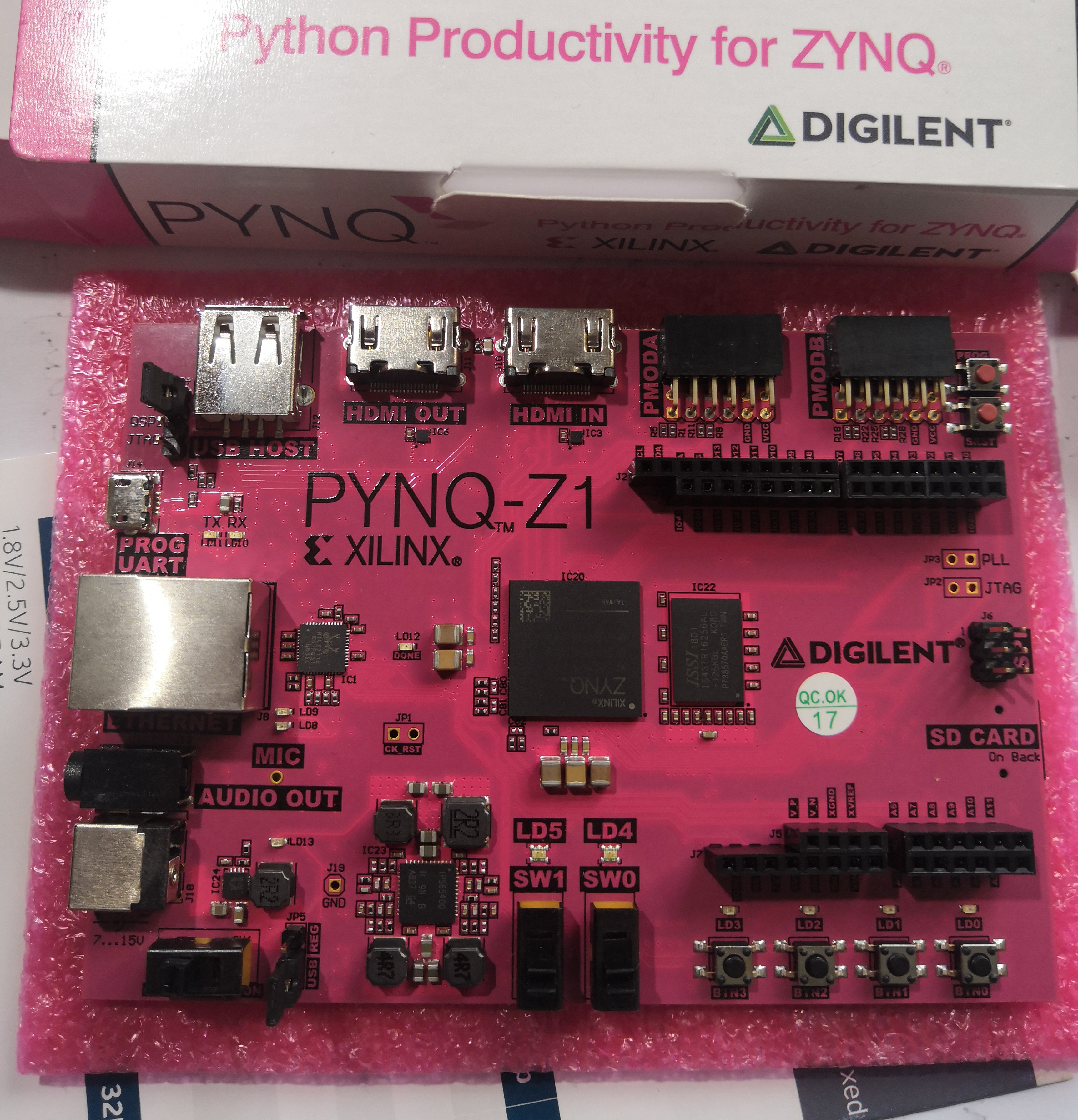
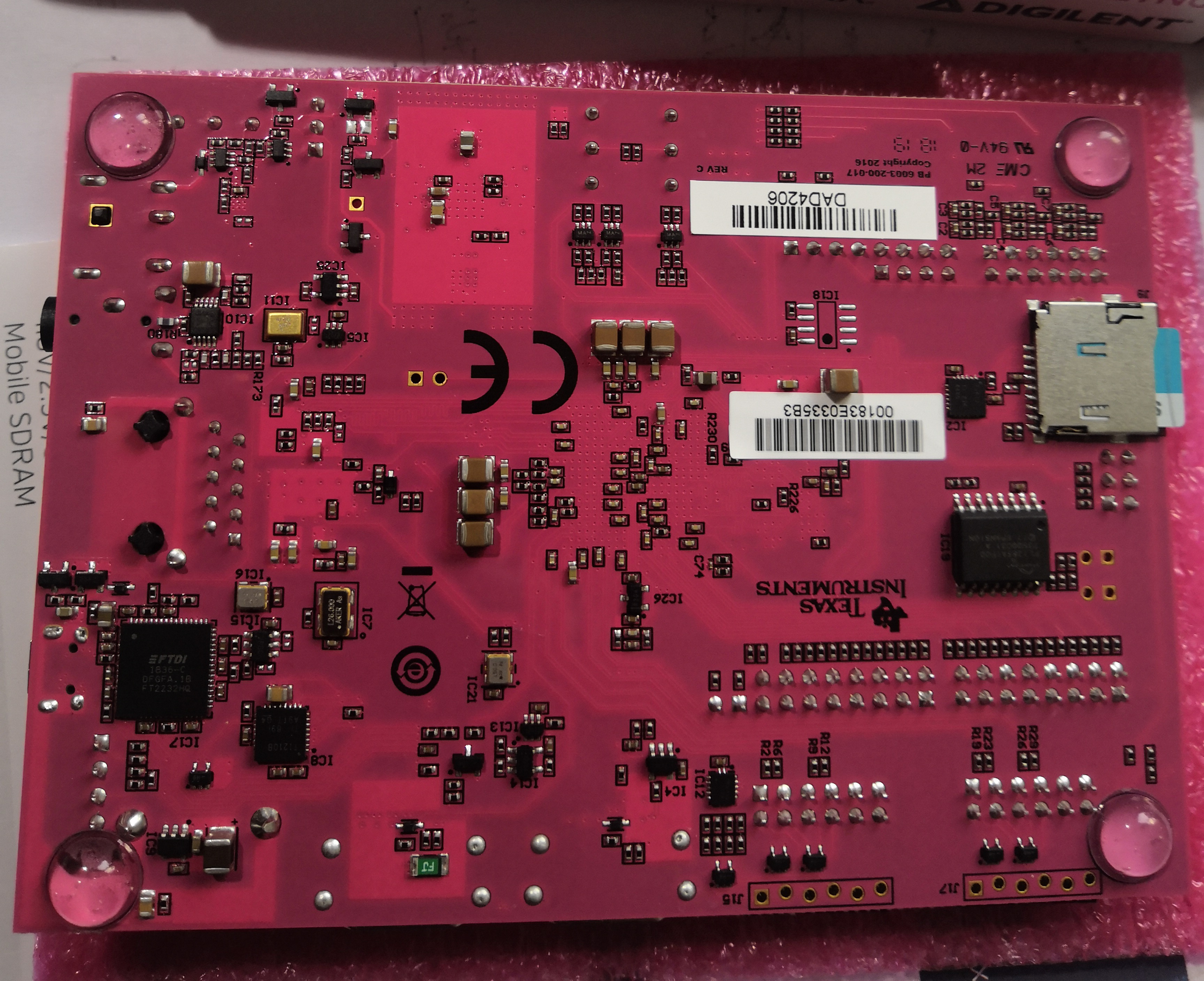
In the middle of the pink(pynq~pink?) PCB is the ZYNQ xz7z020 SoC. On the four side there are peripherals as described on the Digilent reference. Compared to other boards, it has an HDMI sink port, but don’t have much LED or any 7-segment display. The footpads on the back make me feel safe.
Compared to other Digilent boards this one looks pretty “simple”: not much chip components and most area is bare PCB. Before the board arrives I think it’s quite rough and have a little doubt about the quality(considering the low price compared to other boards like ZYBO or Nexys), but when holding it in my hand I find it really delicate and secure.
Tutorial Begin Now
Never forget the document!
I also found this quite helpful.
I spent a lot of effort to get the board(and other functions) working, even after reading the docs again and again for hours. This won’t be a detailed tutorial, but I hope you can save some time, avoid some traps and get some better understanding after reading.
I hope I’ll have time to write a series of tutorials about setup and test, block design, overlay, PS/PL interface, and my project(Monte Carlo on FPGA).
Power On Test: Programmable Logic
To test the PL only a microUSB wire is needed for powering and data downloading, no SD card is needed. Connect the board PROG UART microUSB to your computer. Make sure the left down corner jumper is set to USB if you are using USB to power the board, and don’t forget to turn on the power switch. Also check the jumper at left top corner, seems it both works with the jumper at SD and UART.
Just like normal boards, Create a Vivado project, add a top module for testing, and download the XDC constrain file as described in documentation, uncommenting lines you use, and generate bitstream. In hardware manager you can see the board. Program the board as usual, and check the results by flipping switches, pushbuttons and checking LEDs.
The board appears in hardware manager.
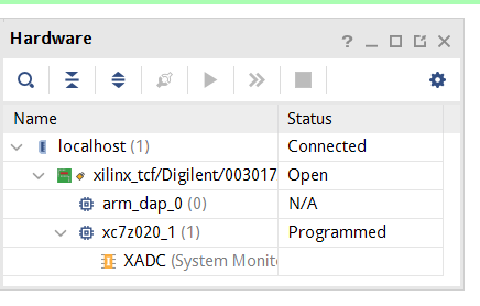
It will work just like normal boards without the two ARM cores, and you can do anything available on other boards on PYNQ, ignoring the processing system, but things will be much more interesting when it comes to the PS.
Boot Test: Linux on SD Card
The document on booting is well-described in the document, just download the image, flash to SD card, check the jumpers, and turn on the switch. My SD card is really slow(~4MB/s continuous write), so it takes about a minute to boot.
If USB drivers are correct, there will be USB serials available.
You can find these in your dmesg:
[1150144.427855] usb 1-1: new high-speed USB device number 53 using xhci_hcd
[1150144.623683] usb 1-1: New USB device found, idVendor=0403, idProduct=6010, bcdDevice= 7.00
[1150144.623689] usb 1-1: New USB device strings: Mfr=1, Product=2, SerialNumber=3
[1150144.623692] usb 1-1: Product: Digilent Adept USB Device
[1150144.623695] usb 1-1: Manufacturer: Digilent
[1150144.623697] usb 1-1: SerialNumber: 003017AD4206
[1150144.629774] ftdi_sio 1-1:1.0: FTDI USB Serial Device converter detected
[1150144.629929] usb 1-1: Detected FT2232H
[1150144.630229] usb 1-1: FTDI USB Serial Device converter now attached to ttyUSB0
[1150144.633097] ftdi_sio 1-1:1.1: FTDI USB Serial Device converter detected
[1150144.633159] usb 1-1: Detected FT2232H
[1150144.633405] usb 1-1: FTDI USB Serial Device converter now attached to ttyUSB1
And these two in lsusb:
Bus 001 Device 053: ID 0403:6010 Future Technology Devices International, Ltd FT2232C/D/H Dual UART/FIFO IC

Bus 001 Device 052: ID 1d5c:5100 Fresco Logic Integrated_Webcam_HD
These two in /dev
/dev/ttyUSB0 /dev/ttyUSB1
If they don’t appear or only some of then appear, try reboot. It takes me two hours just to find out I forgot to reboot after a kernel upgrade.
Then you can connect to the serial. I just use the serial for temporary testing.
screen /dev/ttyUSB1 115200
Press enter and get a terminal.
xilinx@pynq:~$ uname -a
Linux pynq 4.19.0-xilinx-v2019.1 #1 SMP PREEMPT Thu Oct 3 17:21:29 UTC 2019 armv7l armv7l armv7l GNU/Linux
xilinx@pynq:~$
Try both ttyUSB0 and ttyUSB1.
You’ve got a terminal but probably nobody want to work in serial: so the next step is to connect the board to PC via ethernet and connect to SSH and Jupyter notebook server, to reveal the real power.
And for me the ethernet connection took me another 2 hours.
Ethernet: the Final(?) Step
Connect the board’s ethernet port to your PC, and assign your computer an static IP address. Here your computer is client, the board acts like “router”, so the IP address is for your computer, instead of the board, don’t be confused. Document say the IP address of the board will be 192.168.2.99, so you should know that the IP address of your computer SHOULDN’T have 192.168.2.99, but other address (would better) in 192.168.2.xxx range, like 192.168.2.111.
My network configuration.
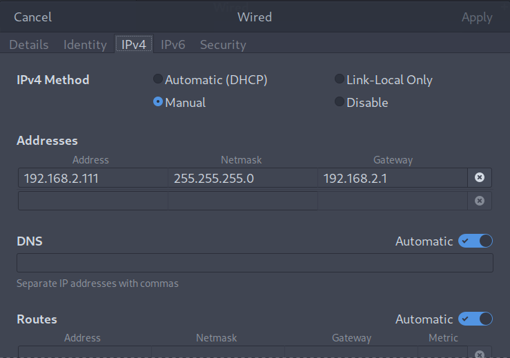
After that you should be able to ping your board at 192.168.2.99. Then you can also SSH into the board, using username and password xilinx. Now a comfortable terminal!
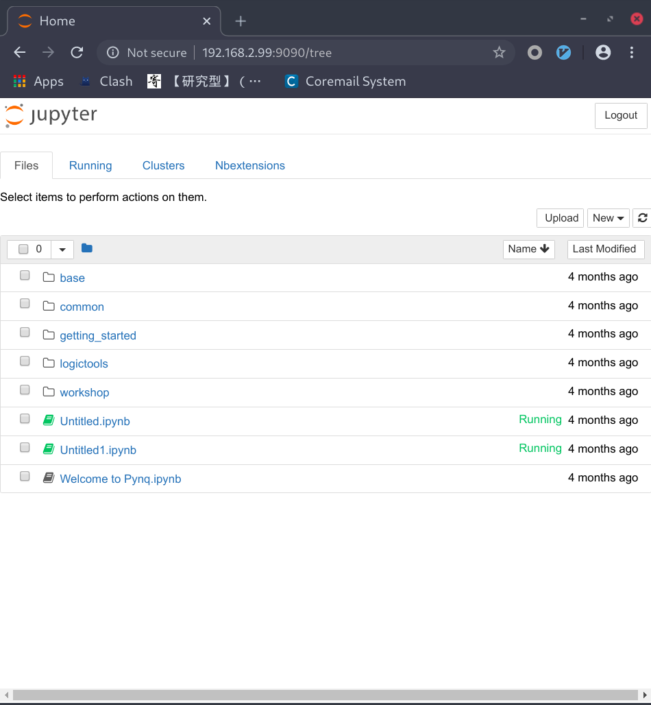
At last, open browser to 192.168.2.99:9090 and you should be able to see the Jupyter notebook. If not check for collision ports.
See you at the next tutorial(or next comic)!
 This work is licensed under the Creative Commons BY-SA 4.0 International License, if not explicitly specified.